

Three specs decide what a filled device does: airflow, heater resistance, and the leak path. Airflow sets how hard the user pulls. Resistance, read with your voltage, sets how much heat the coil makes. The leak path sets where oil goes when pressure or temperature changes. Settle all three in writing before you approve a sample. Fill complaints that reach a brand later are usually decided here, months earlier.
What each of the three controls
| Spec | What it changes for the user | What you should have in writing |
|---|---|---|
| Airflow: intake, airway path, adjustable range | Draw effort, vapour volume, how fast the draw tightens over a fill | Intake configuration, adjustable or fixed, mouthpiece bore |
| Heater resistance at your voltage band | Heat at the coil, behaviour from cold, the last third of the fill | Resistance for the exact model, preheat band, working band |
| Leak path: pressure equalisation, fill level, orientation | Oil at the mouthpiece, on the contact, or in the pack | Where pressure equalises, rated fill volume, storage test |
None of the three can be judged alone. A resistance number without a voltage band describes half a circuit. An intake size without the mouthpiece bore describes half a path. A leak test that only stands the unit upright covers half the journey to the customer.
Airflow: the intake hole is only half of it
Buyers often reduce airflow to one number, the size of the intake. The draw is set by the whole path: the intake, the space around the core, and the mouthpiece bore. Two devices with the same intake can feel different, because the airway volume behind that intake is different.
On a disposable, airflow is fixed or adjustable. Adjustable airflow gives the user a range, and the range has to be specified, not just its existence. Selected models in our range use a 1.8-2.0 mm four-hole intake. On the D159 and D160 the intake is postless with dual airflow, which changes where air enters relative to the heating surface, not only how much enters.
Thick oil changes the maths. Oil at room temperature moves slowly through a porous core. The vapour is denser, and more likely to condense in the airway. A short path with a wide mouthpiece clears condensate differently from a long path with a narrow bore. When a user says the draw tightens over a fill, the finding usually belongs to the airway, not the intake hole. The core side of that finding is covered in why ceramic cores clog with thick distillate.
One habit helps: judge the draw every twenty draws. Write down the draw number where it changes. A draw that holds across a fill and a draw that tightens from draw 20 are different devices, even on the same spec sheet.
Resistance: read it with your voltage
Resistance is not a quality grade. It is one half of a pair. At a fixed voltage, a lower resistance draws more power. A higher resistance draws less. A resistance quoted without a voltage band says little about how a device will behave with your oil.
Our current models run 0.8-1.2 ohm, with 0.95 ohm on one of them. The value is set per model, and specified against the oil and the device. Working voltage is typically 1.8-3.1 V and is customizable; one customer required 3.3 V for their own filling line.
Three questions are worth asking before you approve a sample:
- What is the resistance for this exact model?
- What voltage band will production run, and is it on the sample confirmation?
- Does the resistance change if I change fill volume or oil?
The third question matters. A device built for a 1 ml fill and a thin formulation is not automatically right for a 5 ml fill and a thick one. The coil has more oil to heat and less time to recover between draws. If the answer is “same heater for all of them”, you have learned something useful about how the spec was made.
Keep the band next to your sample record. A test run at one voltage on a device that production fills at another is not a test of the production device.
Leakage: four places oil leaves a device
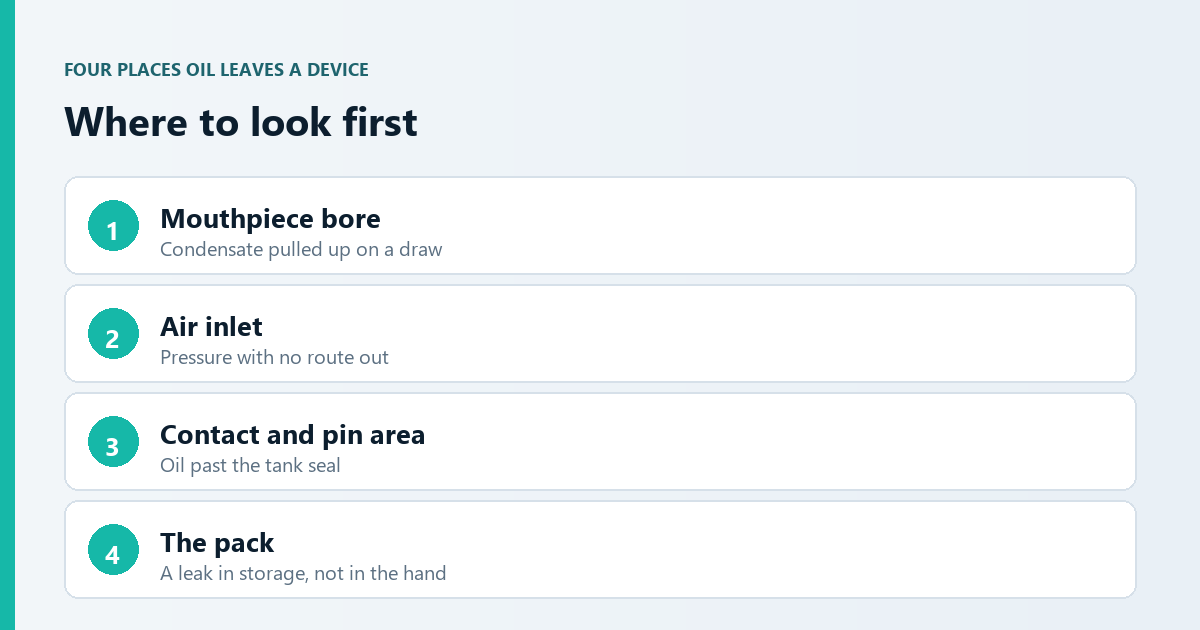
Oil reaches the outside through a short list of paths. Naming them shortens the conversation with a supplier.
The mouthpiece bore. Condensate collects in the vapour path and is pulled up on a draw. What looks like a leak is often condensate with nowhere to settle.
The air inlet. The inlet is part of the pressure-equalisation path. Fill, cap, then move the device through a temperature change, and the air inside expands or contracts. If that pressure has no route, oil is pushed out at the weakest seal.
The contact and pin area. Oil that reaches the contact shows as a wet pin, or a device that will not charge cleanly. It usually means oil travelled past the tank seal, not through the airway.
The pack. Marks inside the carton mean the device leaked in storage. That is a different finding from a leak in the user’s hand. It points at fill level, capping, or how the cartons were stacked.
Four things drive all of them. Oil filled above the rated volume. A temperature swing between the fill room and the warehouse. Oil that thins as it warms. Condensate with nowhere to go.
The design side matters. In our tri-channel ceramic body, a central vertical channel holds the heating element. Two side channels carry oil and let pressure equalise, so the heating surface is fed by more than one path. That is not a leak guarantee. It is a set of paths a buyer can ask about, model by model.
Run the check the way a product travels. Stand the unit upright, then lay it on its side. Wipe the mouthpiece and the air inlet at each step. Record what you see, not whether you liked it. Our sample test record lists the fields we suggest.
Put the three on one page before you approve
A specification sheet for a filled device should fit on one page. These fields belong on it:
- Intake configuration, and whether airflow is adjustable, with the range in millimetres or marked positions
- Mouthpiece bore and material
- Heater resistance for the exact model, plus the preheat and working bands
- Pore size and porosity as a pair
- Rated fill volume and fill tolerance
- Storage orientation to test, and the temperature range the product will see
- Battery capacity and charging interface
Two of these belong together. A core with high porosity and small pores holds more oil and feeds it slowly. A wider pore at the same porosity feeds faster and holds less. On our tri-channel body we specify 55% ± 5 porosity with 8 micron pores, and the pair is chosen for thick oil. If a supplier quotes a pore size alone, ask what porosity it is paired with. A pore number alone does not describe a feed rate.
FAQ: airflow, resistance and leakage
What resistance should I choose for thick oil?
There is no single correct number. Resistance has to be read with your voltage band, your fill volume, and how your oil behaves cold and warm. Our current models run 0.8-1.2 ohm, set per model. Ask for the value for the exact model and band in writing, then test at that band.
Will a bigger air intake stop the draw from tightening?
Not by itself. A draw that tightens late in a fill is usually condensate collecting in the airway, or a core that cannot refill the heating surface fast enough. A larger intake can make it worse if condensate has nowhere to settle.
My sample only leaks when it lies on its side. Why?
Orientation changes which part of the device sits under oil. Check the fill volume against the rated volume, whether the pressure-equalisation path is open, and the temperature the unit saw before the test.
Can airflow be changed after tooling?
Adjustable airflow can be specified on a model that supports it. A change to the intake geometry or the bore changes a moulded part, so it lands in tooling, not in a settings sheet. That belongs at the specification stage. Which commercial model you are buying under — OEM, ODM or white label — is a separate decision from the spec itself.
What do I need to send to get the right specification?
Five inputs: fill volume, how your oil behaves cold and warm, the draws you expect per fill, the temperature range of your market, and the device format and battery you want.
Where this fits a project
If you are choosing hardware for your own oil, settle these three first. They decide how your sample test will read. We develop the hardware and manage the project; the oil, the filling and destination compliance stay with you. Send the five inputs and you will get a reply within one business day with a proposed starting specification.
Once the airflow and resistance band is fixed, the oil itself still decides the core, the intake and the fill volume. The four choices are mapped by viscosity band in how to choose vape hardware for your oil.